MAX7219 Dot Matrix LED Display Control with Arduino
The MAX7219 is a popular integrated circuit (IC) that is widely used to control dot matrix LED displays. It is commonly used in various electronic devices, such as digital clocks, scoreboards, and displays in public transportation systems. In this tutorial, we will show you how to use the MAX7219 with an Arduino board to control a dot matrix LED display.
Required Materials
- Arduino board
- MAX7219 driver IC
- Dot matrix LED display
- Jumper wires
- Breadboard
Overview
The MAX7219 is a serially controlled IC that is designed to drive an 8x8 LED matrix or a 7-segment display. It can be connected to an Arduino board to control a dot matrix LED display, which consists of multiple LEDs arranged in a matrix pattern. The MAX7219 simplifies the process of controlling the display, as it takes care of multiplexing the LEDs and driving the rows and columns.
The dot matrix LED display we will use in this tutorial has 8 rows and 8 columns, for a total of 64 LEDs. Each LED can be individually controlled, allowing us to display patterns, text, and graphics on the display.
Circuit Diagram
The following circuit diagram shows how to connect the MAX7219 and dot matrix LED display to an Arduino board:
Connection Steps
- Connect VCC of the MAX7219 to 5V on the Arduino board
- Connect GND of the MAX7219 to GND on the Arduino board
- Connect DIN (Data In) of the MAX7219 to digital pin 12 on the Arduino board
- Connect CS (Chip Select) of the MAX7219 to digital pin 10 on the Arduino board
- Connect CLK (Clock) of the MAX7219 to digital pin 11 on the Arduino board
- Connect the dot matrix LED display to the MAX7219 according to its pinout.
Code
To control the MAX7219 with an Arduino, we will use the LedControl library, which provides functions for controlling the display. The following code initializes the MAX7219 and displays a pattern on the dot matrix LED display:
#include <LedControl.h>
// Define the number of devices we are using and the pins for the MAX7219
const int devices = 1;
const int slaveSelectPin = 10;
const int dataPin = 12;
const int clockPin = 11;
// Create a new instance of the LedControl library
LedControl lc = LedControl(dataPin, clockPin, slaveSelectPin, devices);
void setup() {
// Initialize the MAX7219
lc.shutdown(0, false);
lc.setIntensity(0, 8);
lc.clearDisplay(0);
}
void loop() {
// Display a pattern on the dot matrix LED display
for (int i = 0; i < 8; i++) {
lc.setRow(0, i, B10101010);
}
delay(1000);
lc.clearDisplay(0);
delay(1000);
}
The setup() function initializes the MAX7219 by setting the shutdown mode to false, the display intensity to 8, and clearing the display.
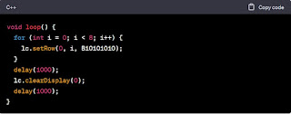
In the loop() function, a pattern is displayed on the dot matrix LED display by setting each row of the display to a binary pattern using the lc.setRow() function. The pattern used in this example is B10101010, which will display diagonal lines on the display.
After the pattern is displayed for one second, the display is cleared using the lc.clearDisplay() function, and then there is a delay of one second before the loop repeats.
Explanation
Let's break down the code line by line:
This line includes the LedControl library, which we will use to control the MAX7219.
setup() function, which is called once when the
Arduino board is powered on or reset. In this function, we initialize
the MAX7219 by setting the shutdown mode to false (which turns the
display on), the display intensity to 8 (which sets the brightness of
the display), and then clear the display.This is the loop() function, which is called repeatedly after the setup() function has completed. In this function, we display a pattern on the dot matrix LED display by setting each row of the display to a binary pattern using the lc.setRow() function. The first parameter of the lc.setRow() function is the device number, which is 0 since we are only using one device. The second parameter is the row number (0 to 7), and the third parameter is the binary pattern to display.
After the pattern is displayed for one second using the delay() function, the display is cleared using the lc.clearDisplay() function. Then there is another delay of one second before the loop repeats.
Conclusion
In this tutorial, we have shown you how to use the MAX7219 with an Arduino board to control a dot matrix LED display. We used the LedControl library to simplify the process of controlling the display. With this knowledge, you can now create your own projects that use the MAX7219 and dot matrix LED displays.


Posting Komentar untuk "MAX7219 Dot Matrix LED Display Control with Arduino"